84 Results
View results:
Sort by:

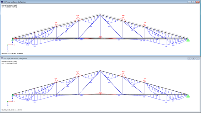
This article describes and explains the influence of bending stiffness of cables on their internal forces. Furthermore, the text provides information on how this influence can be reduced.
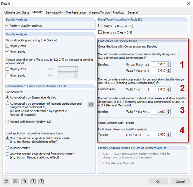
For situations where no design is available, RF-/STEEL EC3 provides the option to neglect the respective internal forces. Examples of such situations are: bending and compression on angle sections, multi-axial bending for the design according to the General Method, torsion.
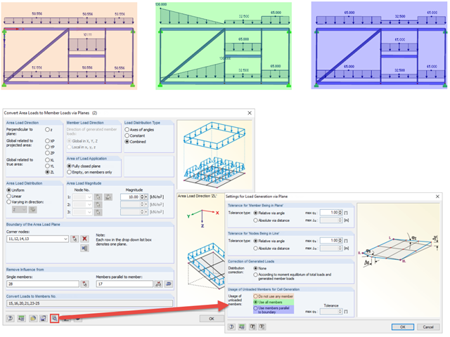
When generating member loads via plane, the program generates cells internally. These cells significantly influence the created member loads.
A successful project process involves not only the building owner and the engineer, but also the designers. These days, they also have to design standard connections in steel structures themselves. To do this, the corresponding internal forces of connections are required.

The determined values for the influence ordinates are displayed as decimal numbers with up to six decimal places by default. This is usually sufficient for the influence lines of internal forces.
In RF-/JOINTS Timber - Steel to Timber, you can consider the eccentricities of a connection during the calculation. The figure shows different internal forces without consideration of the eccentricity (above) and withn consideration of the eccentricity (below).
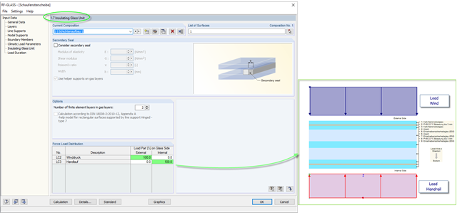
The insulating glass pane design places a special requirement on the load application point of the loading. For example, wind loads and loads due to fall protection may appear. For this, the wind load should be applied on the external glass side and the handrail load should act on the internal glass pane.
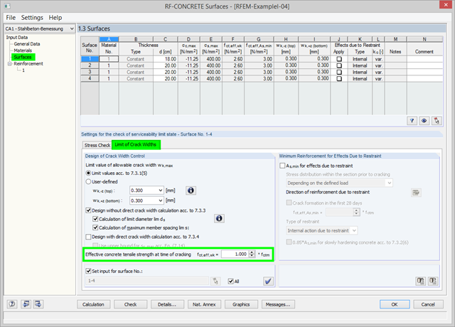
As of RFEM Version 5.06, there is the option in RF‑CONCRETE Surfaces to adjust the effective concrete tensile strength at the time of cracking. At the start of the SLS design, the program checks whether the internal forces can cause cracks in the concrete. For this, the effective concrete tensile strength at the time of cracking is applied. You can adjust the strength via the factor. The calculation details display the adjusted value.

With RFEM version 5.06, member stiffnesses can be influenced by methods that are aligned with US steel construction standard ANSI/AISC 360-10. According to this standard, reduction factor τb must be considered for the determination of internal forces in all members of which the flexural resistance contributes to the model's stability. This coefficient depends on the axial force in the member: The larger the axial force, the larger τb is.
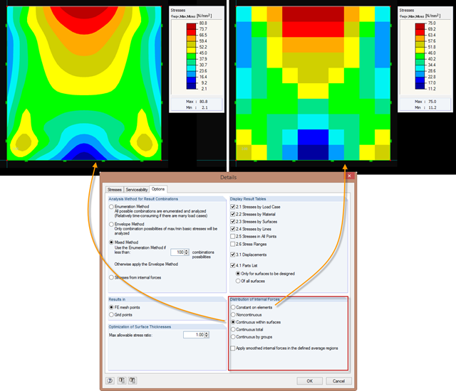
Just as in the RFEM Display Navigator, you can set the distribution of internal forces in surfaces in RF‑STEEL Surfaces. Since deformations are always the result of the FEM calculation, the corresponding forces will be recalculated. This means that the internal forces on an FEM element are calculated depending on the composition (triangular or square) in three or four places. In order to obtain continuous internal forces and thus a smoothed distribution, these internal forces have to be interpolated. Interpolation is done by selecting the "Distribution of internal forces" option in the surfaces.

If you want to use a pure surface model, for example, when determining the internal forces and moments, but the structural component is still designed on the member model, you can take advantage of a result beam.
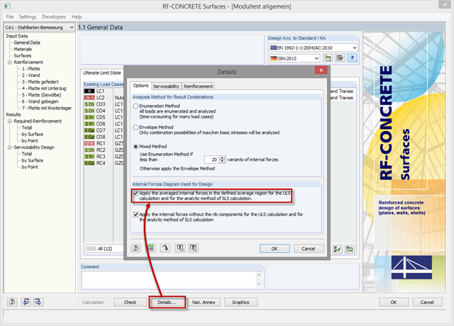
In order to use internal forces from average regions also for the design of concrete surfaces, you have to activate them in the module. For this, click the [Details] button in the "Tools" tab and select the option "Apply the averaged internal forces in the defined average region for the ULS calculation and for the analytic method of SLS calculation."
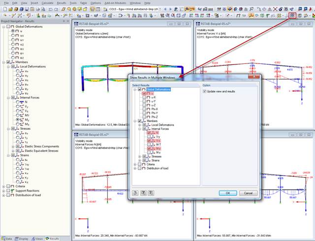
In order to show various results (deformations, internal forces) in multiple windows quickly, you can use the "Arrange Result Windows" function ("Results" menu). A dialog box appears where you can select the relevant results to be displayed.
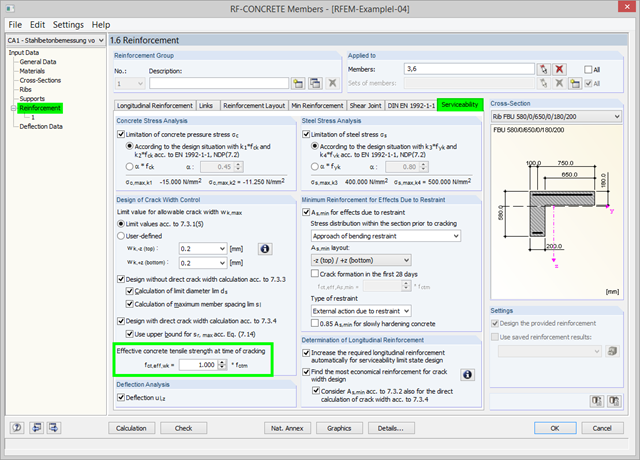
As of program version 5.06, you can use the option to adjust the effective concrete tensile strength fct,eff,wk at the time of cracking. At the start of the SLS design, the program checks whether the internal forces can cause cracks in the concrete. For this, the effective concrete tensile strength at the time of cracking is applied. You can adjust the strength via the factor. The calculation details display the adjusted value.

In RFEM 5 and RSTAB 8, it is possible to assign nonlinearities to member hinges. In addition to the nonlinearities "Fixed if" and "Partial activity", you can select "Diagram". If you select the "Diagram" option, you have to specify the according settings for the activity of the member hinge. For the individual definition points, it is necessary to specify the abscissa and ordinate values (deformations or rotations and the according internal forces) that define the hinge.
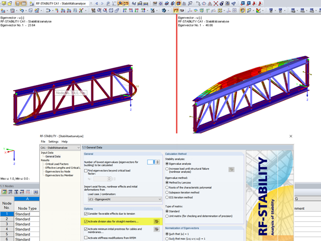
When analyzing structural elements susceptible to buckling by using the modules RF‑STABILITY (for RFEM) or RSBUCK (for RSTAB), it might be necessary to activate the internal division of members.

As you may already know, RFEM 6 offers you the possibility to consider material nonlinearities. This article explains how to determine internal forces in slabs modeled with nonlinear material.

In RFEM 6, the results for the FE mesh nodes are determined using the finite element method. For the distribution of internal forces, deformations, and stresses to be continuous, these nodal values are smoothed through an interpolation process. This article will introduce and compare the different types of smoothing that you can use for this purpose.
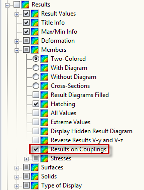
In order to display the internal forces of rigid members, it is necessary to select the corresponding option under ‘Results’ → ‘Members’ → ‘Results on Couplings’ in the Display navigator.
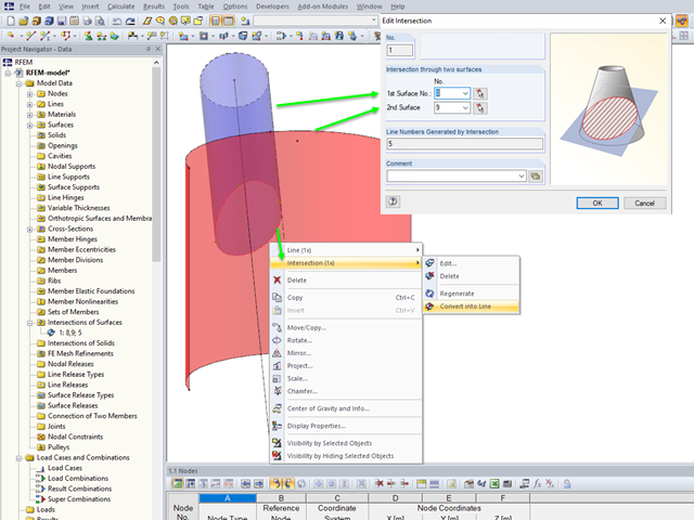
If you want to model two intersecting surfaces, RFEM offers you the possibility to create the section line automatically. In the program, this function is referred to as intersection. When generating an intersection, the modeled surface is split into components. This has the advantage that the components can be taken into account in the determination of the internal forces, or deactivated.

RF‑CONCRETE Surfaces for RFEM 5 allows you to use averaged internal forces for design of concrete surfaces.

The add-on modules for designing structural member components according to national, European, and international standards also show design results in addition to numerical output in tables graphically, as diagrams displayed on the framework.

RSECTION 1 is a stand-alone program for determining section properties for both thin-walled and massive cross-sections, as well as for performing a stress analysis. In addition, the program can be connected to both RFEM and RSTAB: sections from RSECTION are available in the RFEM/RSTAB libraries, and internal forces from RFEM/RSTAB can be imported into RSECTION.

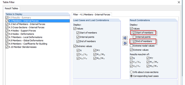
By means of result combinations, it is possible to create, among other things, the envelopes for internal forces and deformations. Thus, you can quickly find the maxima and minima for the subsequent design.
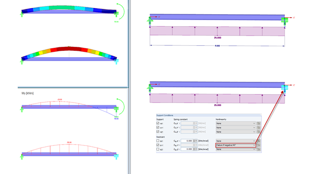
In practice, an engineer often faces the task of representing the support conditions as close to the reality as possible in order to be able to analyze the deformations and internal forces of the structure subjected to their influence and to enable construction that is as cost efficient as possible. RFEM and RSTAB provide numerous options for defining nonlinear nodal supports. This second part describes the options for creating a nonlinear support for a restraint and provides a simple example. For a better understanding, the result is always compared to a linearly defined support.
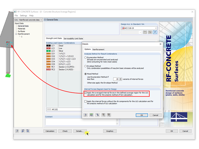
The averaged internal forces from the previously defined average regions can also be used for designing concrete surfaces. To do this, click [Details] in RF‑CONCRETE Surfaces, then select the corresponding check box. This function is accessible only if you previously defined an average region.
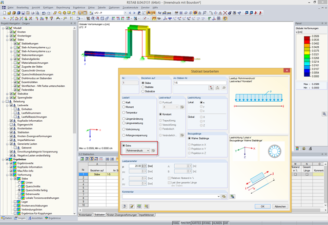
In addition to bending, torsional, longitudinal, and strain loads, you can define and analyze the internal pressure of members with circular hollow cross‑sections in RFEM and RSTAB. The following perimeter and axial stresses resulting from the internal pressure load are analyzed using Barlow's formula and transferred to design modules in order to superimpose the remaining stresses due to internal forces.

For the design of concrete surfaces, the rib component of the internal forces can be neglected for the ULS calculation and for the analytical method of the SLS calculation, because this component is already considered in the member design. To do this, select the check box in the "Details" dialog box. If no rib was defined, this function is not available.

The stand-alone program RSECTION is at your disposal for determining section properties and performing stress analysis for thin-walled and massive cross-sections. The program can be connected to both RFEM and RSTAB so that sections from RSECTION are also available in the RFEM and RSTAB library. Likewise, internal forces from RFEM and RSTAB can be imported into RSECTION.
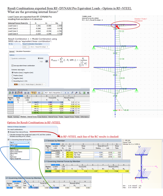
Result combinations exported from RF‑/DYNAM Pro – Equivalent Loads are generated by superimposing the results from the individual modal responses. For this, the SRSS rule can be used as "equivalent linear combination". When result combinations are used in RF‑/STEEL, two options are available for calculating stresses. In the first option, the results from the result combinations are used directly. This is done line by line, for each maximum and minimum controlling internal force. In the second option, stresses are determined from the individual load cases. The quadratic superposition rule is then performed again in RF-/STEEL.